
Selection Guide
SAMIFLEX COUPLINGS
Method
Data required for coupling selection:
- Application details (for service factor)
- Horsepower and RPM of the driver
- Shaft details of the driving and driven equipment
- Determine the service factor (SF) from the application and classification list below.
- Calculate the maximum HP/100 RPM rating: HP/100 rpm = (HP x 100 x SF)/RPM Select the coupling which has a higher max rating.
- Compare the maximum RPM capacity & bore requirements to the catalog limits for the coupling selected
Example
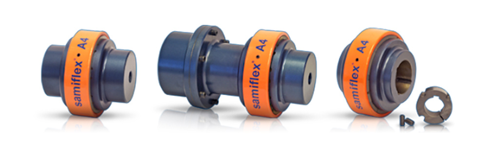
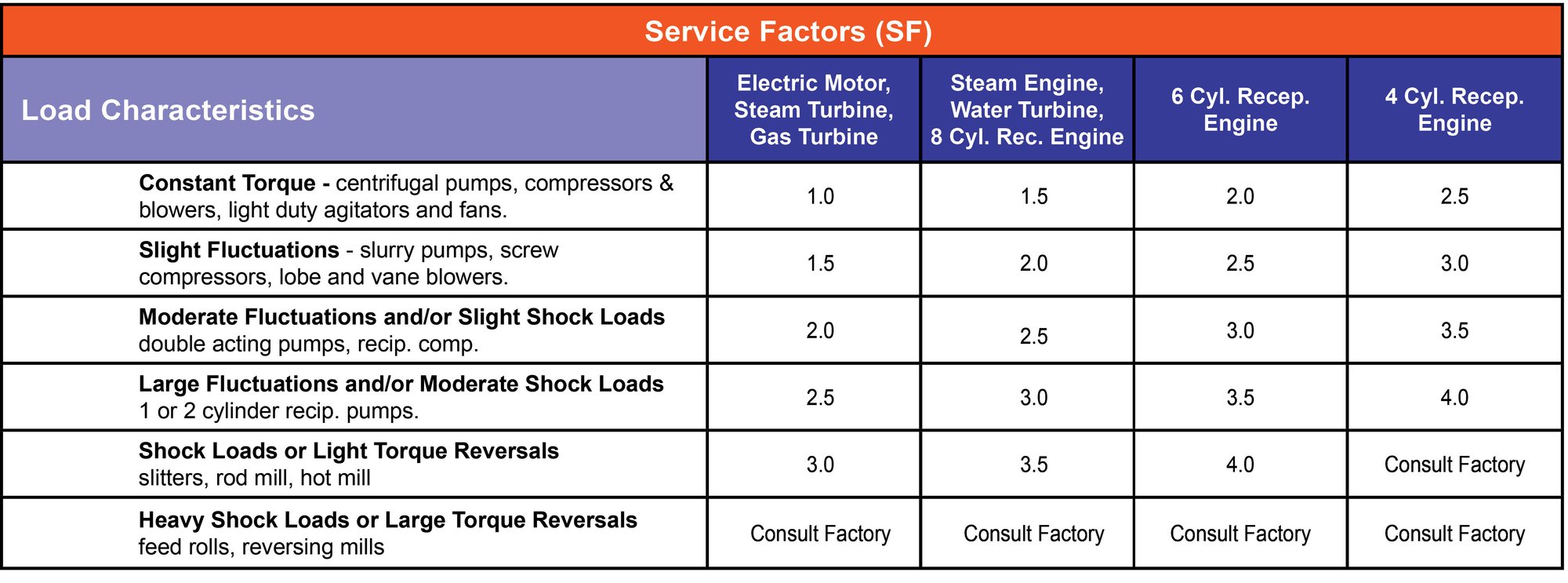
Driver: water turbine (100 HP at 1800 rpm)
Driven equipment: screw compressor
Turbine bore: 2.38” Compressor bore: 2.00”
Distance between shaft ends (DBSE): 5”
Service factor for the water turbine & screw compressor: SF=2
HP/100 RPM = (100 HP x 100 x 2) / 1800
HP/100 RPM = 11.1
Coupling selection based on max rating: A4B
Coupling bore capacity: 2-7/8”
The maximum speed for A4B is 3275 RPM unbalanced
DBSE for A4B is 5”. A4B is acceptable in this application

- Use a minimum service factor of 1.25 when driving through a gearbox or using a direct online electric motor.
- Consult CDWdrives when using a reciprocating engine with fewer than 4 cylinders.
- The service Factors provided are for reference only. Customers' experience may dictate the selection of different service factors.